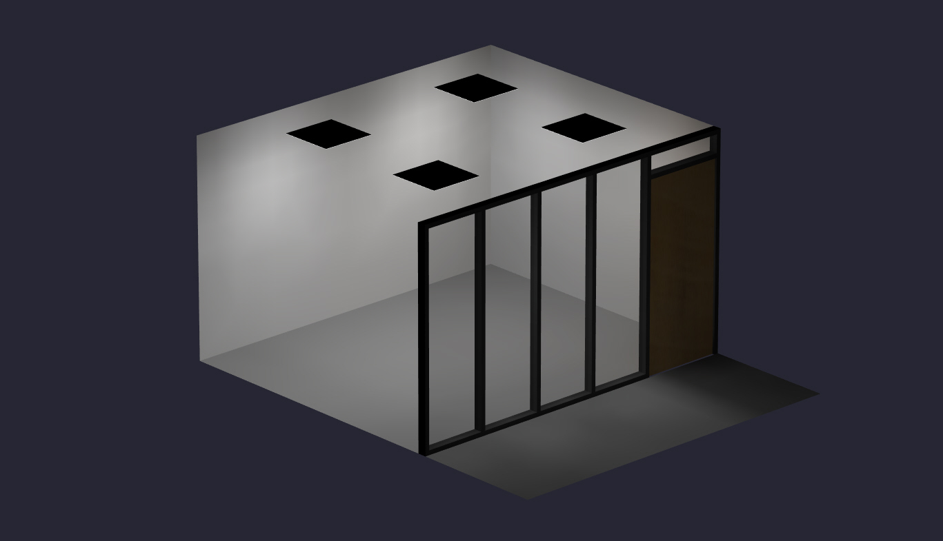
A rendering of a curtain wall, complete with mullions and a wooden door. How could its complexity be reduced while still delivering meaningful results?
Including vs. Omitting Glass Elements in Lighting Simulation
Modeling glazing can be essential to accurate lighting simulation, but elements such as curtain walls, glass wall partitions, and windows do not significantly interact with light in every calculation situation. Because of this, they are modeled at a simulation engineer’s discretion. The following simulations show how omitting a clear glass wall partition can affect results.
Model Details
The following AGi32 model shows two versions of an office adjacent to a corridor segment. In both:
In Version A, the glass wall partition between the office and corridor is not modeled; it is left as a wall with standard reflectance (50%). In Version B, the glass wall partition is modeled as glass with a transmittance of 90% (note: framing elements have been omitted).
The most apparent benefit of choosing Version A over Version B is time. Modeling glass elements takes more time because separate material properties must be assigned to all or portions of a wall.
Rendering of Version A (left) and Version B (right) with all lights on. Note: black separation boxes not visible.
In the following simulations, we will see how turning on and off the office and/or corridor lights affects the illumination results of each space.
Simulation #1
In Simulation #1, only the office lights are on:
Version A
The office troffers contribute no light to the corridor and, because the glass wall is treated as a solid wall, the light is reflected back into the room. If a designer were looking for an average of 35+ foot-candles in the office, this model would suggest that the target is being met.
Version B
The office light passes through the glass wall and contributes a significant amount of light to the corridor. Because the wall is not reflecting light back into the office, the office’s average falls below our designer’s minimum foot-candle average of 35.
Simulation #2
In Simulation #2, both the office and corridor lights are on:
Version A
As expected, the office illumination does not change in a meaningful way. The illumination now present in the corridor is only a result of the corridor luminaires. If a designer wanted a minimum average of 25 foot-candles in the corridor, this simulation would not suggest that the goal is met.
Version B
In addition to the corridor light, the office light passing through the glass wall contributes to the corridor values. This model’s results would significantly exceed a 25 foot-candle minimum. Note that, because the aperture of the corridor lights is not particularly wide, it contributes little light to the office and the results remain similar to those from Simulation #1.
Simulation #3
In Simulation #3, only the corridor lights are on:
Version A
As expected, the corridor values change in no meaningful way and there is no light in the office.
Version B
Some light passes into the office, but the results are only somewhat significant in calculation points closest to the glass wall. Version B’s corridor values don’t differ significantly from those in Version A. While Simulation #2 suggested that Version B would meet the designer’s minimum 25 foot-candle average, we see that, if the office lights are off, that target would not be met.
Summary
Modeling glass features is a decision that a simulation engineer must make when balancing time with modeling accuracy. While overmodeling wastes time, undermodeling can deliver inaccurate results. Here, we are some further thoughts based on the results:
Omitting Glass Modeling
Simulation #3 shows how light doesn’t always interact with nearby walls enough to impact values. This is because the interaction with nearby objects depends on luminaire output, beam angle, mounting position, and distance from the wall. The following pseudo color render of an exterior window illustrates a situation where 2’x4′ troffers are offset from the exterior wall:
It makes little difference whether or not the window is modeled in this room.
A render with pulled-down and half-closed blinds. Not much light makes it to the corridor.
Another reason for omitting glass wall and window modeling could be blinds. For example, if our office had blinds installed with about 50% LRV and the office will usually have the blinds closed, it may make sense to leave the glass wall as a standard wall.
Glass modeling can provide complete, highly accurate simulation results. These results can offer us a better idea of whether or not project goals are being met. For example:
Simulation #1 showed that modeling the glass wall as a solid would indicate that target office levels were being met due to the walls reflection. Appropriately modeling it as a glass wall revealed that values were not met.
Simulation #2 showed how modeling the glass wall as glass indicates that target corridor values were being met.
Simulation #3 clarified that Simulation #2’s achievement of corridor target light levels was the result of spill-over office light (demonstrating the value of running both combined and isolated calculations in interior glass wall situations).
A simulation with no corridor lights (but plenty of light in curtain wall-adjacent corridors).
Conclusion
The differences in results draws attention to the importance of disclosing what has and hasn’t been modeled. For example, if a simulation engineer were to omit all glass for the sake of time, that would need to be communicated to the designer. Depending on the situation, the designer may be able to make reasonable predictions of lighting interaction that is missing from the model.
Unless otherwise requested, Vela Photometrics generally models interior glass wall patitions as glass with 90% transmittance (while omitting framing elements). Calculations are provided as combined (all lights on), with isolated (circulation/occupied space only) calculations available upon request. Note that other factors such as blind-use, frosting, and door material may alter this standard. Exterior glass walls and windows are modeled on a case-by-case basis.